Poker-face warning: this is not an April Fool's gag (weren't quite clever enough this year!)
A couple of years ago
I built a very large dining table for my home. It will seat ten comfortably, and several more if needed.
But I've held off on building chairs due to my inexperience with this furniture genre. The past couple years I've done a lot of research on chair types, or more accurately, chair-construction methods. I've spent a lot of my shop time making tree trunks into
precise rectangles. So I thought it would be a good idea to branch out
into a style of building that I was unfamiliar with. That led me towards the work of John Brown and his Welsh stick chairs.
His book stayed in my mind long after I closed the last page, and the pair of Welsh stick chairs by Chris Schwarz that I keep in my office serve as a constant reminder of this more rudimentary, non-rectangular construction style.
Next I considered the work of Jeff Miller. Jeff is not only a friend, but he's also been a big influence and sounding board for new ideas in woodworking techniques. His chairs are undeniably comfortable and beautiful, but I felt like I needed to go even further back to an earlier evolutionary stage to find what I was looking for. Jeff makes his chairs with a combination of ancient and modern techniques, but I wanted something more ancient.
Then, in the middle of this process Konrad Sauer started building a set of chairs for his dining table and that got my mind reeling with yet another option. Konrad's interpretation of Maloof's joint was intriguing, but again I found myself drawn to the rudiments of the craft.
But as I usually do, I find myself returning full circle.
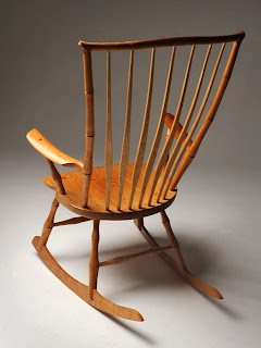
I've followed the work of Peter Galbert for a number of years, and aesthetically his more modern chairs have appealed to me the most. However, I'm not a huge fan of the classic windsor chair (in all its varieties), but I have become quite a fan of the windsor technology. Call it green woodworking, stick chairs, whatever. I simply think it makes a lot of sense to build a chair this way, and for the way I want to work, it's enormously appealing. Of course Peter's work has greatly influenced my decision to try this method.


To test my theory I decided to build one of Peter's Smarthead shaving horses. The project itself uses chairmaking technology, so I thought it would be a good exercise to answer some of my curiosities. Last year I drew up plans in Sketchup for the Smarthead portion, but before I got a chance to build one Pete made a bunch of refinements to the design and asked if I would mind making the changes to the plans. I was happy to oblige. So after many long nights after work and numerous emails back and forth with Pete, I decided to completely redraw the Smarthead. I then generated 2-d plans of all the components. I also drew a Sketchup drawing of Pete's shavehorse to supplement the Smarthead plans.
To download the 2-d prints of the Smarthead,
click here.
To download the Sketchup drawing of the Smarthead Shavehorse,
click here.
The Sketchup drawing does not show the tapered dowels nor their matching angled holes in detail. They are simply represented in the drawing. To understand how the dumbhead is secured to the Smarthead, and also how the housing is secured to the plank, see
Pete's video.
Update: Pete tells me that he's working on making some proper 2-d prints of the shavehorse. Stay tuned to Pete's blog for updates. I will post here too when they are available.
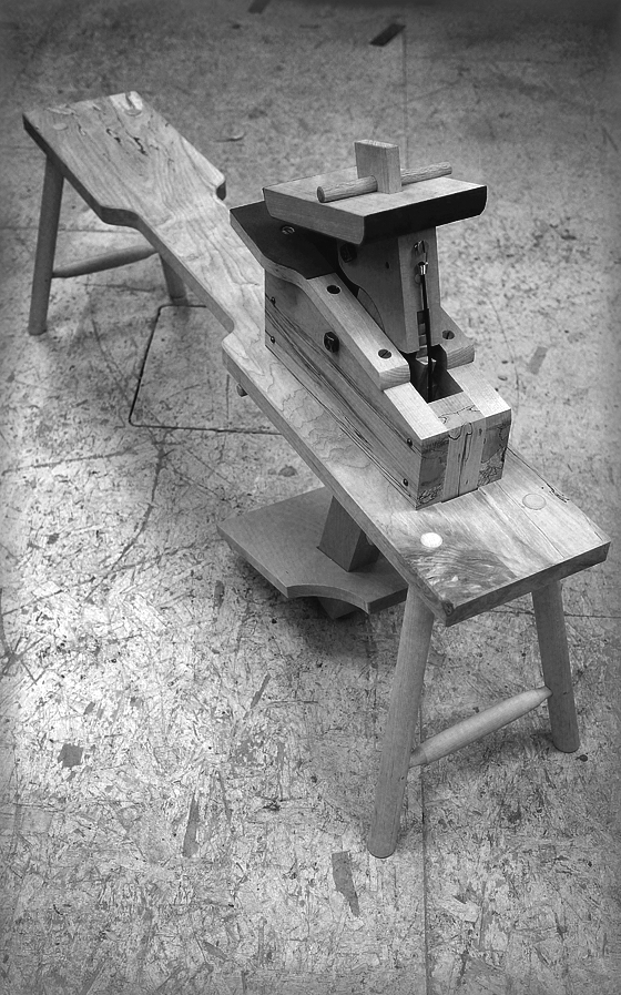
With plans in hand, I headed out to the shop to build my first shavehorse.
With help from Pete and Steve's sightline ruler I laid out my sightlines for the splayed legs of the plank. I didn't have enough width on the plank to lay out for the rake, so I butted another board to the edge to get the intersection.
Once I had the first sightline established, I set a bevel gauge to the angle and laid out the other three.
Tim Manney's reamer is simply a joy to use. I don't have a mirror or laser setup yet (being rectified at the moment) so I simply eyeballed the angle with a bevel gauge and square.
But before I could test my reaming job I had to turn some legs.
The first pair of legs were a tad off.
But the second pair were better.
By the time I had the holes reamed, and the legs fit, I had my answer. This was the way I'd build my chairs.
This is how I drilled the legs for the stretchers. Don't laugh, my lasers will be here tomorrow....
The plank is spalted maple. It's solid around the legs.
The legs are not glued or wedged into the plank, but simply tapped firmly into the tapered holes. This allows the horse to knock down for storage and transport.
With the plank and legs done, I focused on the housing and the Smarthead. The latter is made exclusively of beech.
I used some square nuts to keep the shafts in place. More on this below.
In use, the upper pivot shaft must end flush with the sides of the Smarthead, otherwise workpieces can get trapped under the exposed portion, in this case the square nut, instead of being held down by the front of the dumbhead. So I removed the nuts, and cut the shaft shorter.
This was one of the funnest projects I've done in a long time. But now the real fun begins. Sourcing wood for my set of dining chairs.


 Made in the U.S.A.